in UX / UI
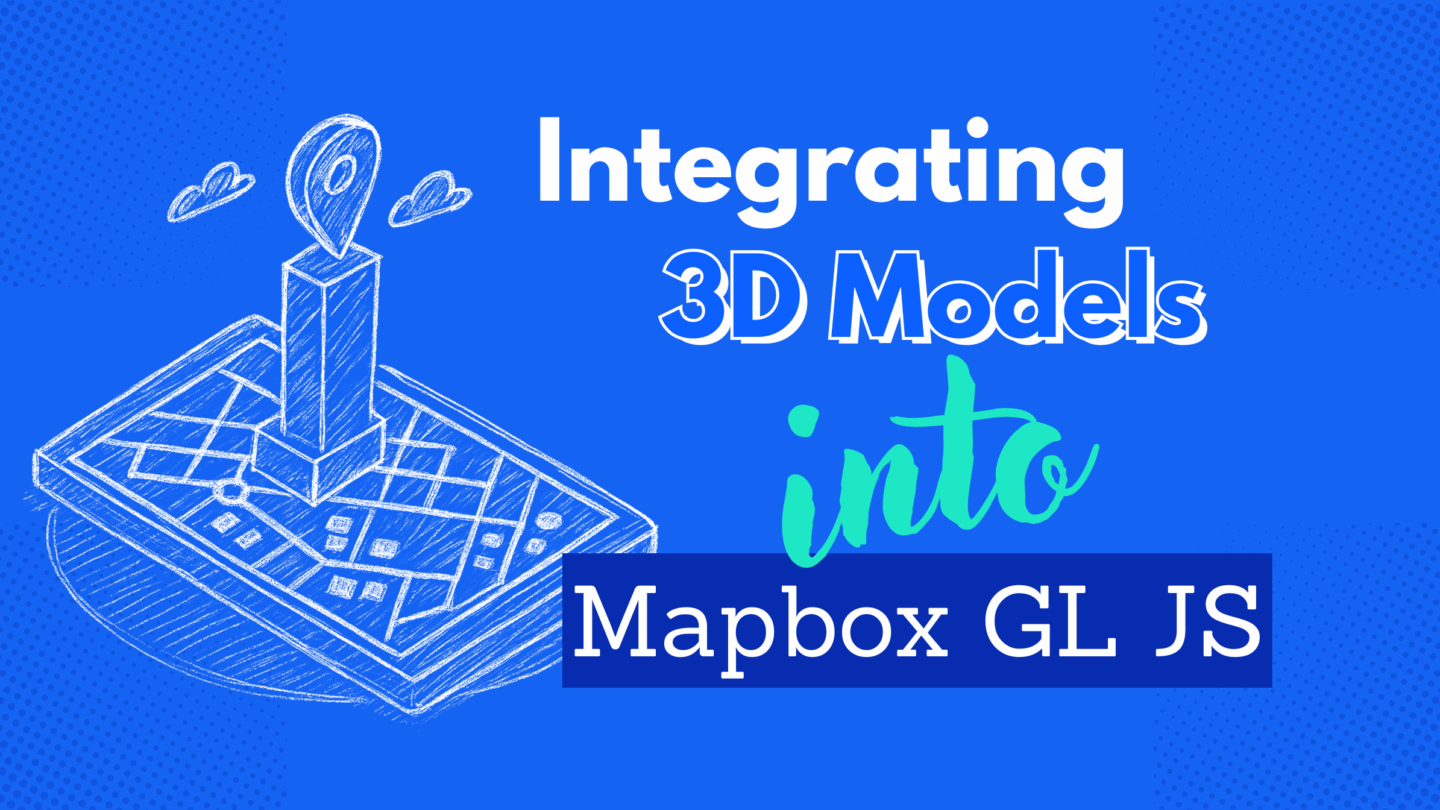
Custom 3D models in Mapbox: a step-by-step integration guide

Mapbox already offers great-looking 3D maps out of the box, but sometimes you need something more specific to tell your story. In this post, I show how I built and integrated a custom 3D model using Three.js to highlight a unique landmark and create a more immersive experience.
The need for unique detail
Imagine you want to showcase a specific building or landmark that isn’t available in the Mapbox Standard 3D dataset. You’re faced with a generic, simplified representation that doesn’t capture the architectural details or significance of the location. How do you bridge this gap and bring your vision to life?
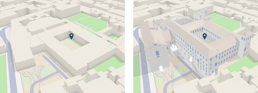
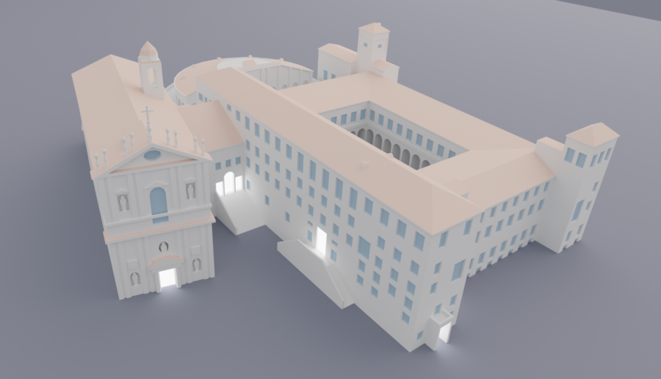
Pontifical University of St. Thomas Aquinas (Angelicum), Rome, Italy in Mapbox Standard – Before and After.
Solving it piece by piece
I followed several important steps, starting with 3D modeling, then integrating the model into the map, and finally fine-tuning the details for the best result.
Gathering measurements: the foundation of an accurate 3D model
Before diving into 3D modeling, precise measurements are crucial. Since architectural plans aren’t always available, I used a combination of tools to estimate dimensions accurately.
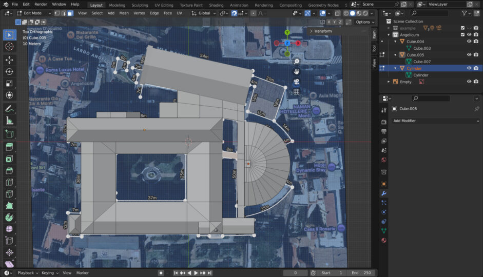
- Google Maps’ measuring tool: I traced the building’s outline and recorded key dimensions.
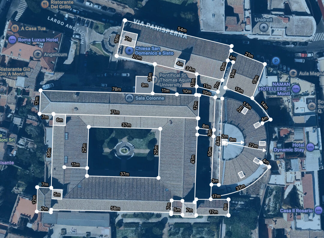
Measuring the building footprint in Google Maps (top view) to gather accurate dimensions for the 3D model.
- Custom ruler method: Using photos with minimal perspective distortion and a graphic editor like Figma, I created visual rulers based on a known width from a top-down satellite view in Google Maps. I divided this reference measurement into equal segments to establish an accurate scale. Then, I rotated the rulers vertically to measure heights and architectural details like doors, windows, ledges, and other elements.
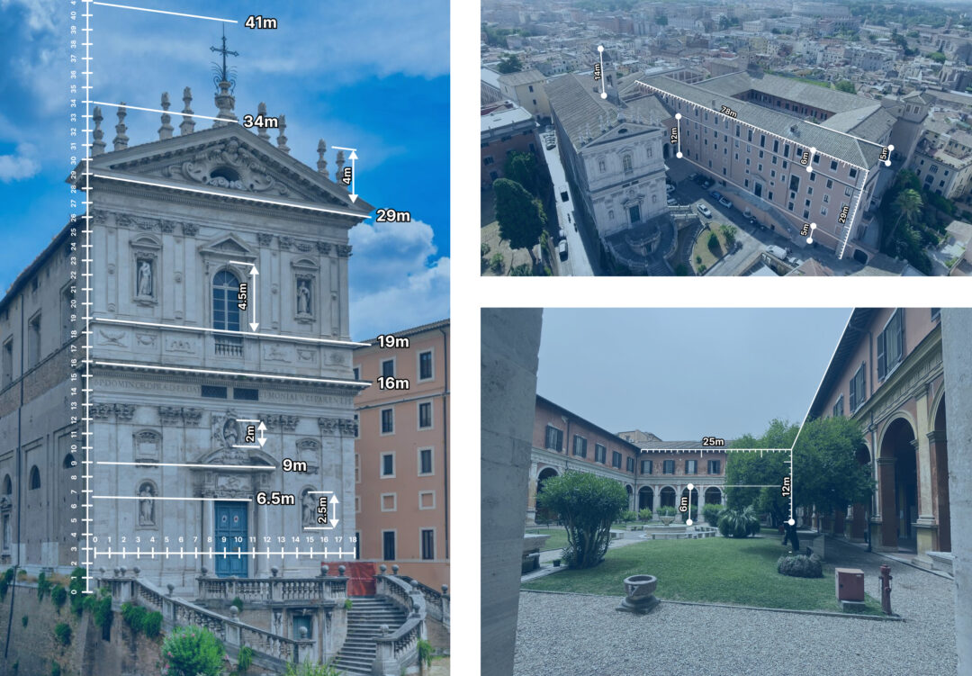
Measuring Up: Using a custom ruler to determine building dimensions from photos.
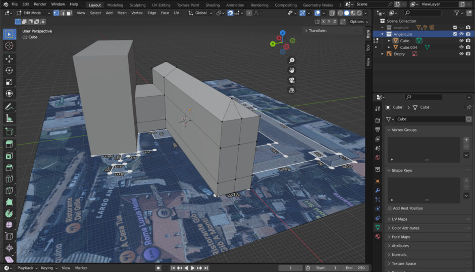
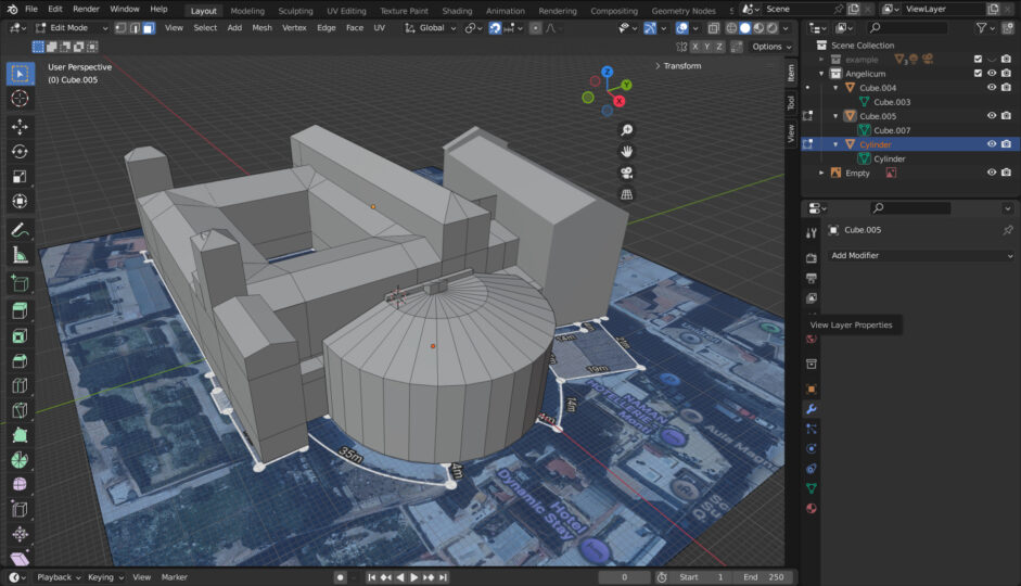
3D modeling in Blender: bringing the model to life
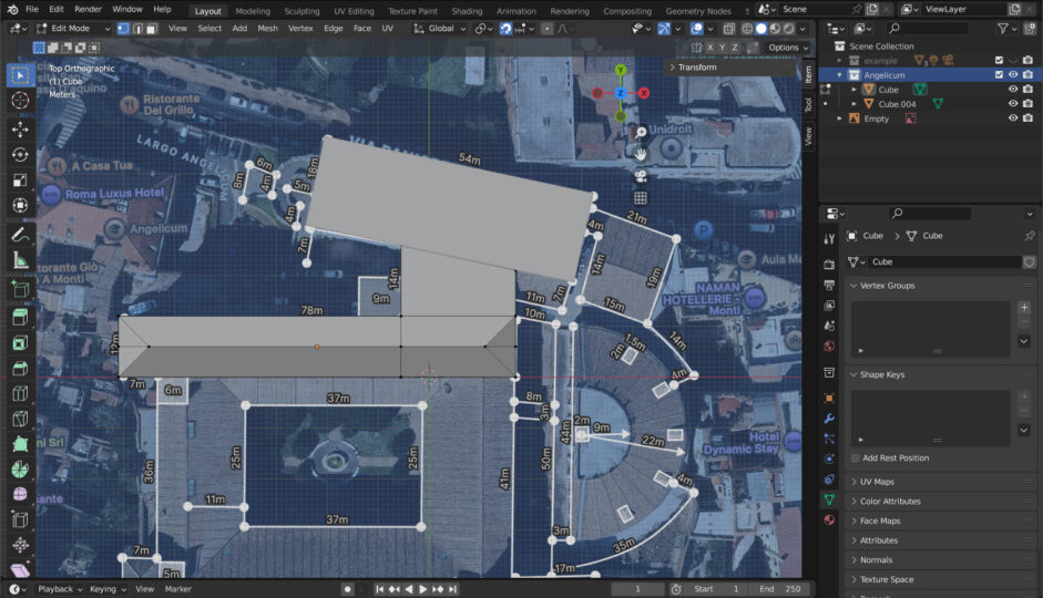
Blender, a powerful and free open-source 3D creation suite, was my tool of choice for modeling. I imported the top-view screenshot with measurements into Blender as a reference image. Using meters as units, I modeled the building, focusing on capturing key architectural features while maintaining a low-poly style consistent with Mapbox’s 3D buildings. My goal wasn’t photorealistic accuracy but a visually appealing and performant representation.
After completing the geometry, I applied initial materials with approximate colors, then refined them during the lighting setup to better match the colors of Mapbox buildings and the surrounding environment.

Exporting the model: preparing for Mapbox integration
Once the 3D model was complete, I exported it as a .glb file. This format is a binary version of .gltf that combines the model, textures, and other assets into a compact file, making it easier to manage. It’s widely supported and optimized for web-based 3D graphics, which makes it ideal for Mapbox integration.
When exporting, I always ensure the model’s scale and orientation are correct to avoid issues during map placement. Applying Blender modifiers beforehand is crucial. For the best results, I use meters as the unit scale, check face orientation to prevent flipped normals, and simplify the geometry where possible to improve performance. If the model includes textures, I make sure they are optimized and lightweight to ensure faster loading times.
If you want to enhance your skills in this area, I highly recommend checking out the Three.js Journey course by Bruno Simon. It’s an excellent resource for learning how to work with Three.js, create and optimize 3D models in Blender, and export them properly for use in Three.js and projects like this one.
Map integration with Mapbox GL JS: where the magic happens
Now for the fun part—digging into the technical details. Integrating the custom model into Mapbox GL JS involves several key steps:
1. Clipping the default building
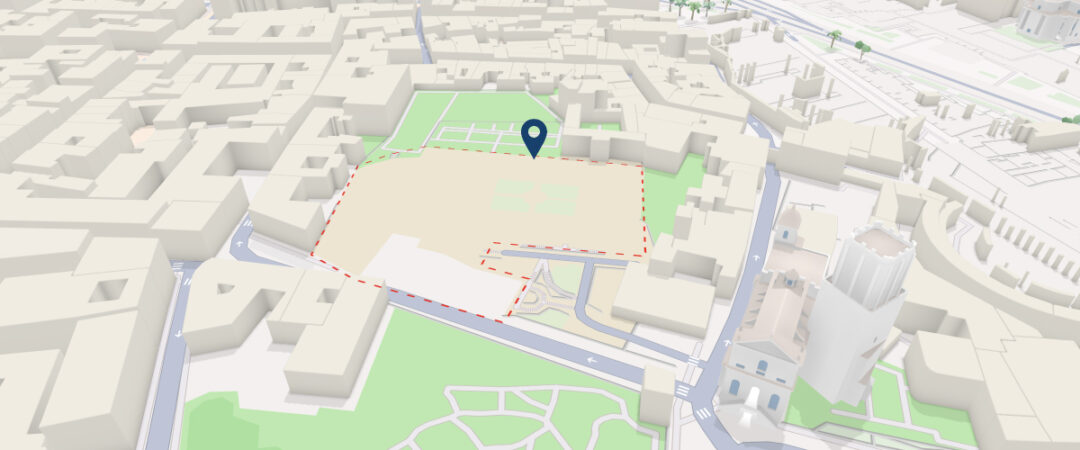
Default building clipped using a custom GeoJSON polygon, making space for the 3D model.
To seamlessly integrate my custom model, I needed to remove the default Mapbox building. I achieved this using Mapbox’s clip layer. First, I created a GeoJSON polygon that precisely outlines the area of the default building, using a tool like geojson.io to draw and export the shape. Then, I added a clip layer to the map, referencing the GeoJSON polygon as its source.
map.addSource('eraser', {
  type: 'geojson',
  data: {
    type: 'FeatureCollection',
    features: [
      {
        type: 'Feature',
        properties: {},
        geometry: {
          // Coordinates that we got from the geojson.io
          coordinates: [
            [
              [12.487380531583028, 41.89565029206369],
              [12.488045110910008, 41.895709818778926],
              [12.488039595728878, 41.89582681940209],
              [12.487824503664086, 41.895841187884514],
              [12.487846564388576, 41.896062872638026],
              [12.4884973557632, 41.89599513571156],
              [12.488748296504838, 41.89593150398784],
              [12.488902721576324, 41.89542655322492],
              [12.488797933134919, 41.895315709840276],
              [12.488654538424868, 41.89522334020583],
              [12.487518411111182, 41.89510223314949],
              [12.487380531583028, 41.89565029206369]
            ]
          ],
          type: 'Polygon'
        }
      }
    ]
  }
})

map.addLayer({
  id: 'eraser',
  type: 'clip',
  source: 'eraser',
  layout: {
    'clip-layer-types': ['symbol', 'model']
  },
  minzoom: 1
})
2. Setting up the 3D model
To integrate a 3D model, I defined its geographic location and transformation parameters.
// Define the origin (longitude, latitude) of the 3D model
const modelOrigin = [12.488160, 41.895612]
// Set the altitude of the model (0 means at ground level)
const modelAltitude = 0
// Define the rotation of the model in radians [X,Y,Z]
const modelRotate = [Math.PI / 2, -12.43, 0]

// Convert the geographic coordinates to Mercator coordinates
// This is necessary because Mapbox GL JS uses Web Mercator projection
const modelAsMercatorCoordinate = mapboxgl.MercatorCoordinate.fromLngLat(
  modelOrigin,
  modelAltitude
)

// Create a transformation object for the 3D model
const modelTransform = {
  // Set the X, Y, Z translations using the Mercator coordinates
  translateX: modelAsMercatorCoordinate.x,
  translateY: modelAsMercatorCoordinate.y,
  translateZ: modelAsMercatorCoordinate.z,
  // Set the rotations around each axis
  rotateX: modelRotate[0],
  rotateY: modelRotate[1],
  rotateZ: modelRotate[2],
  // Calculate the scale factor
  // This ensures the model is sized correctly relative to the map
  scale: modelAsMercatorCoordinate.meterInMercatorCoordinateUnits()
}
3. Adding a custom 3D model layer to Mapbox
I added a custom layer to the Mapbox map to render the 3D model. This involved setting up a Three.js scene within Mapbox GL JS, loading the model, and configuring the rendering pipeline. Here’s how the custom layer was structured:
map.addLayer({
  id: '3d-model',
  type: 'custom',
  renderingMode: '3d',
  onAdd: function (map, gl) {
    // Set up Three.js scene, camera, lights, and load the 3D model
  },
  render: function (gl, matrix) {
    // Render the 3D model
  }
})
For a full breakdown, see the official Mapbox GL JS 3D model example.
4. Loading the GLTF/GLB model
I used GLTFLoader from Three.js to load the model.
onAdd: function (map, gl) {
  // ...
  const loader = new GLTFLoader()
  loader.load('path/to/model.glb', (gltf) => {
    // Traverse through the model’s scene graph
    gltf.scene.traverse((child) => {
      if (child.isMesh) {
        // Enable shadows only for meshes
        child.castShadow = true
        child.receiveShadow = true
      }
    })
    this.scene.add(gltf.scene)
  })
}
The gltf.scene.traverse((child) => {...}) function loops through all the meshes within the model, allowing for selective enabling of shadow casting and receiving. This capability is particularly useful when models contain elements that should not cast or receive shadows, such as transparent or background meshes.
5. Adding lights and configuring shadows
Ambient and directional lights
I used an ambient light for general illumination and two directional lights to nicely light up the model and cast shadows:
onAdd: function (map, gl) {
  // ...
  const ambientLight = new THREE.AmbientLight(0xffffff, 2)
  this.scene.add(ambientLight)

  const directionalLight = new THREE.DirectionalLight(0xffffff, 1)
  directionalLight.position.set(-40, 250, 150)
  directionalLight.castShadow = true
  directionalLight.shadow.bias = -0.003
  this.scene.add(directionalLight)

  // Second directional light to illuminate the model from another side
  const secondaryLight = new THREE.DirectionalLight(0xffffff, 0.5)
  secondaryLight.position.set(50, 100, -50)
  this.scene.add(secondaryLight)
}
Shadow configuration
To improve shadow quality and reduce artifacts, I increased the shadow map resolution and adjusted the shadow camera’s near, far, left, right, top, and bottom properties:
directionalLight.shadow.mapSize.width = 1024
directionalLight.shadow.mapSize.height = 1024
directionalLight.shadow.camera.near = 0.1
directionalLight.shadow.camera.far = 500
directionalLight.shadow.camera.left = -100
directionalLight.shadow.camera.right = 100
directionalLight.shadow.camera.top = 100
directionalLight.shadow.camera.bottom = -100
If the shadow camera’s frustum is too large or too small, it can cause precision issues in the shadow map. Therefore, it is important to ensure the frustum tightly fits the area where shadows are needed.
Fixing shadow acne issue
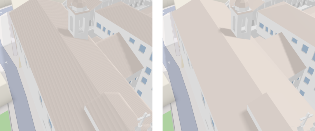
Shadow rendering before and after bias adjustment.
Shadow acne refers to visual artifacts that appear as a „ladder“ or striped texture on surfaces. It occurs because the shadow map’s depth values are compared to the scene’s depth values, and small precision errors can cause incorrect shadowing. The shadow.bias property offsets the shadow map slightly to avoid these errors.
directionalLight.shadow.bias = -0.003Tips:
- Start with a small value (e.g., -0.001) and adjust as needed.
- If the bias is too high, shadows may appear detached from objects.
6. Adding shadow cast on the map surface
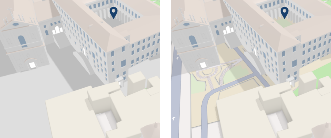
Default grey plane compared with ShadowMaterial applied.
In Blender, I added a plane to the 3D model to serve as a surface for receiving shadows. After importing the model into Three.js, I located the plane by its name in the scene graph and applied a ShadowMaterial to it.
gltf.scene.traverse((child) => {
 //...
 if (child.isMesh && child.name === 'Plane') {
    child.material = new THREE.ShadowMaterial()
    child.material.opacity = 0.1
    child.receiveShadow = true
  }
})
This ensures the shadow of the model is visible on the map surface.
7. Rendering the scene
Finally, I updated the Three.js camera and rendered the scene within Mapbox’s render function of the custom layer:
//...
render: function (gl, matrix) {
  const rotationX = new THREE.Matrix4().makeRotationAxis(
    new THREE.Vector3(1, 0, 0),
    modelTransform.rotateX
  )
  const rotationY = new THREE.Matrix4().makeRotationAxis(
    new THREE.Vector3(0, 1, 0),
    modelTransform.rotateY
  )
  const rotationZ = new THREE.Matrix4().makeRotationAxis(
    new THREE.Vector3(0, 0, 1),
    modelTransform.rotateZ
  )

  const m = new THREE.Matrix4().fromArray(matrix)
  const l = new THREE.Matrix4()
    .makeTranslation(
      modelTransform.translateX,
      modelTransform.translateY,
      modelTransform.translateZ
    )
    .scale(
      new THREE.Vector3(
        modelTransform.scale,
        -modelTransform.scale,
        modelTransform.scale
      )
    )
    .multiply(rotationX)
    .multiply(rotationY)
    .multiply(rotationZ)

  this.camera.projectionMatrix = m.multiply(l)
  this.renderer.resetState()
  this.renderer.render(this.scene, this.camera)
  this.map.triggerRepaint()
}
8. Final touches and enhancements
Adjusting material colors
At this point, I adjusted the material colors of the roof, walls, and windows in Blender to better match the surrounding Mapbox buildings. This created a more cohesive appearance, helping the custom 3D model blend seamlessly into the scene. Using Mapbox’s „Day“ light preset along with my lighting setup, I finalized the following color values:

Fixing model distortion on resize
When shadows are enabled, resizing the window can cause the model to appear distorted because the shadow calculations aren’t automatically updated. To resolve this, I dispose of the renderer and reinitialize it whenever the window is resized:
onAdd: function (map, gl) {
  // ...
  const handleResize = () => {
    this.renderer.dispose()
    this.renderer = new THREE.WebGLRenderer({
      canvas: map.getCanvas(),
      context: gl,
      antialias: true
    })
    this.renderer.shadowMap.enabled = true
    this.renderer.shadowMap.type = THREE.PCFSoftShadowMap
    this.renderer.autoClear = false
  }

  map.on('resize', handleResize)
}
Simulating Mapbox’s glowing entrance effect
To replicate Mapbox’s signature glowing entrance effect, I started by creating a 3D mesh in the shape of an upside-down square arch.
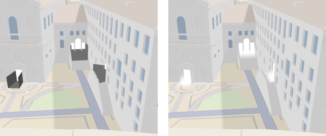
Comparison of the entrance mesh before and after applying the „glowing“ shader.
Next, I applied a custom shader to the mesh to simulate a soft, glowing effect. The shader creates a gradient that goes from white at the back to full transparency at the edges, creating the illusion of soft light emanating from the entrance.
gltf.scene.traverse((child) => {
  //...
  if (child.isMesh && child.name.startsWith('Door_Glow')) {
    const gradientMaterial = new THREE.ShaderMaterial({
      vertexShader: `
        varying vec2 vUv;
        varying float vDepth;
        varying float vHeight;

        void main() {
          vUv = uv;
          vDepth = position.z;
          vHeight = position.y;
          gl_Position = projectionMatrix * modelViewMatrix * vec4(position, 1.0);
        }
      `,
      fragmentShader: `
        varying vec2 vUv;
        varying float vDepth;
        varying float vHeight;

        void main() {
          vec3 color = vec3(1.0, 1.0, 1.0);
          float backToFront = smoothstep(-1.0, 1.0, vDepth);
          float topToBottom = smoothstep(-1.0, 1.0, vHeight);
          float alpha = backToFront - topToBottom;
          gl_FragColor = vec4(color, alpha);
        }
      `,
      transparent: true
    })

    child.material = gradientMaterial
  }
})
For those interested in diving deeper into shaders, I recommend again checking out the Three.js journey by Bruno Simon (https://threejs-journey.com/) and The Book of Shaders (https://thebookofshaders.com/).
Final result
Conclusion
Integrating custom 3D models into Mapbox GL JS maps truly opens up a world of exciting possibilities for visualizing unique locations and creating highly engaging user experiences. As I’ve explored in this detailed breakdown, overcoming the technical challenges involved in this process allows for the creation of truly stunning and informative 3D map applications.
If you’re curious about how advanced 3D map integration could elevate your next project – or simply have questions you’d like to explore – feel free to reach out and see what we can build together.